
Say something terrible has happened to your t-amp TA2400 power amplifier, something disastrous like the outputs of two amplifiers being connected to each other, and then the amplifiers driven with radically different signals. The likely result of this kind of abuse will be the destruction of all 8 output transistors, and the blowing of the two 16A fuses on the PCB of the channel in question. The obvious symptom will be:
- The channel won’t work
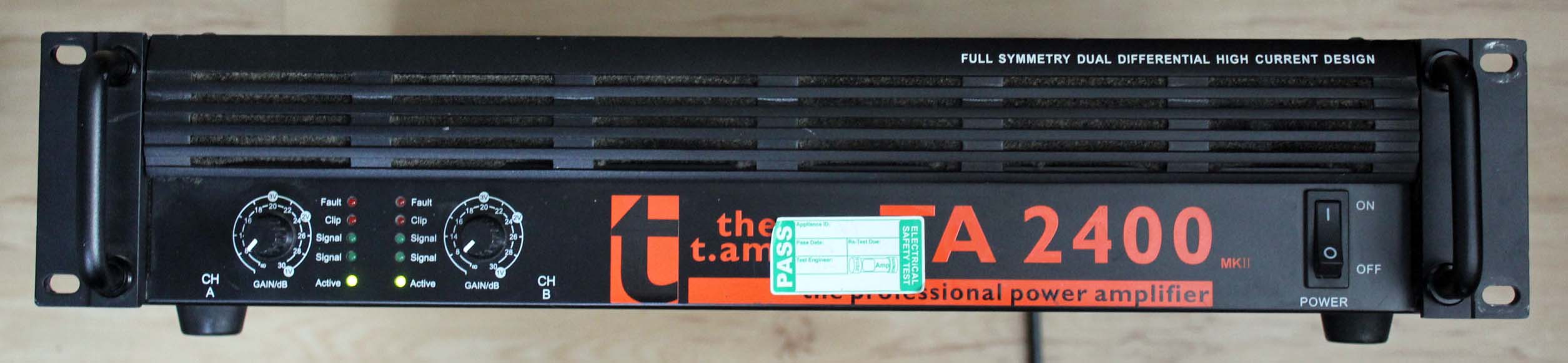
- The clipping LED will be lit, even with no drive
In this case, it’s Channel A (left) that is b0rked.

TA2440 front panel, clipping LED on
First port of call was to email Thomann UK to try and get hold of a schematic. Their piss-poor response was that one wasn’t available. No matter, we can freestyle it.
Disconnect from the mains and remove the top panel.
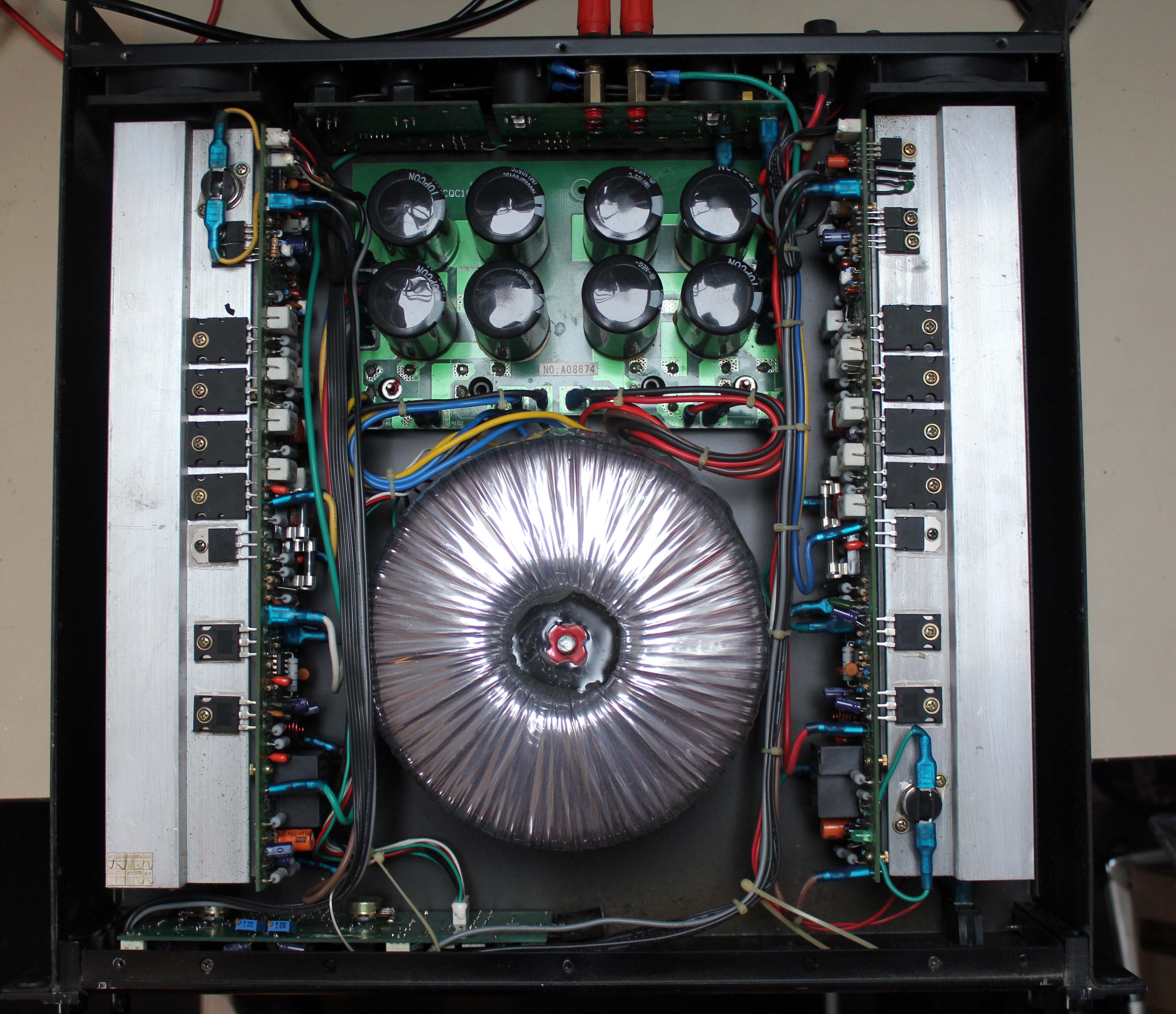
TA2440 top cover removed
Remove the four screws underneath that attach the heat sink assembly to the chassis baseplate. This will make it easier to disconnect the push-on connectors from the spades on the PCB.
TA2440 channel A heatsink assembly detail
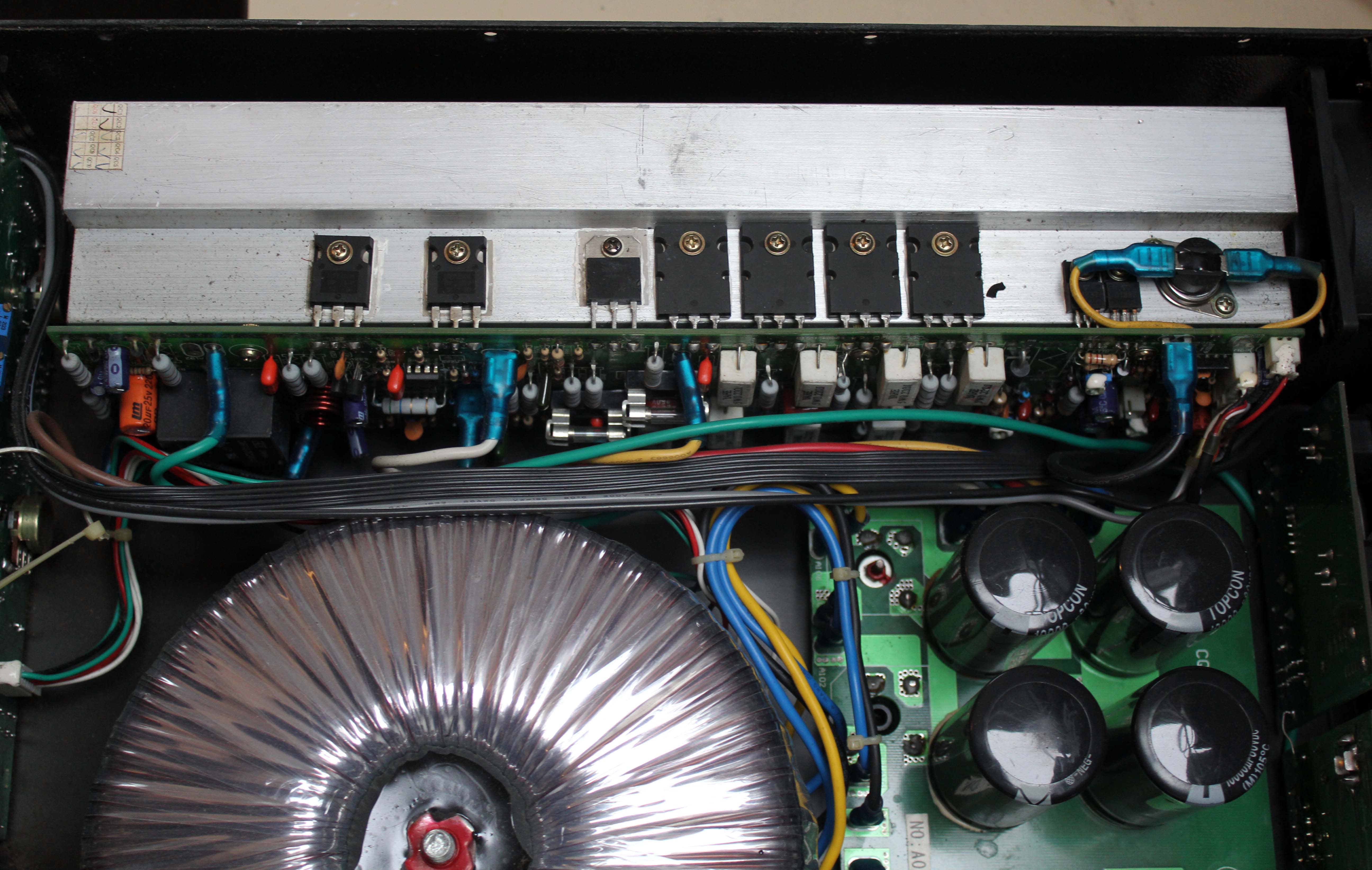
Make a careful note of what colour wire goes to which connector on the PCB. If the connectors are stiff, pull back the insulating sleeve so you can get in with a small pair of connectors. Be careful you don’t rip the spades off the PCB.
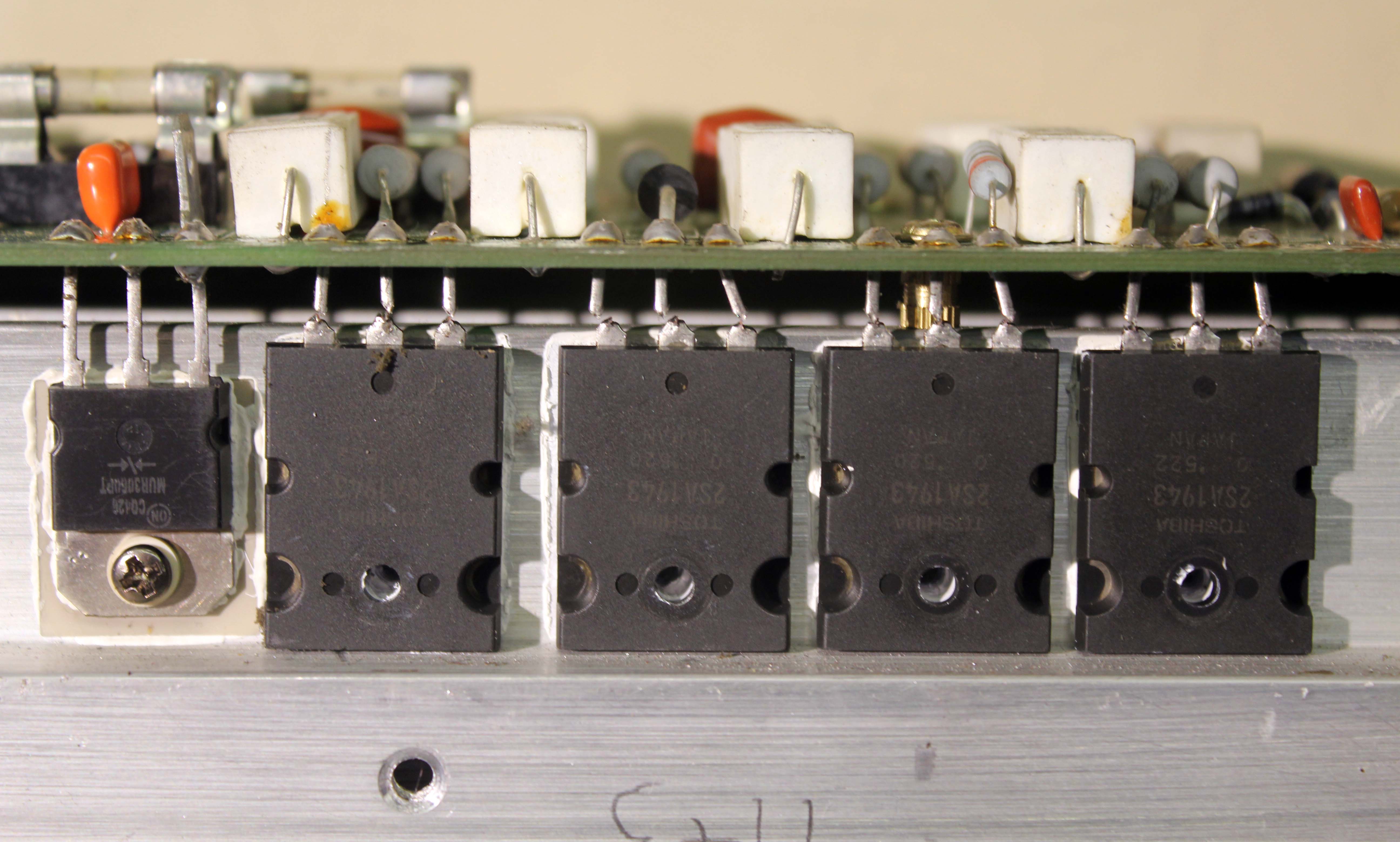
TA2440 channel A heatsink assembly removed
The output stage is made of a 4 2SA1943 PNP transistors hanging off the positive rail and 4 2SC5200 NPN transistors hanging off the negative rail.
Laughing in the face of Design For Manufacturability, Thomann have designed the A and B amplifier assemblies to be weird mirror images of each other, rather than using the same assembly for both. This means on channel A (left) the NPN transistors are uppermost, whilst on channel B (right) the PNP transistors are uppermost.
Use a DMM (digital multimeter) to do a diode test on the power transistors). This is complicated by the presence of low resistance paths on the PCB. Despite these, it should be bleeding oblivious which transistors have been fucked, as the diode test will show close to 0V in both directions.
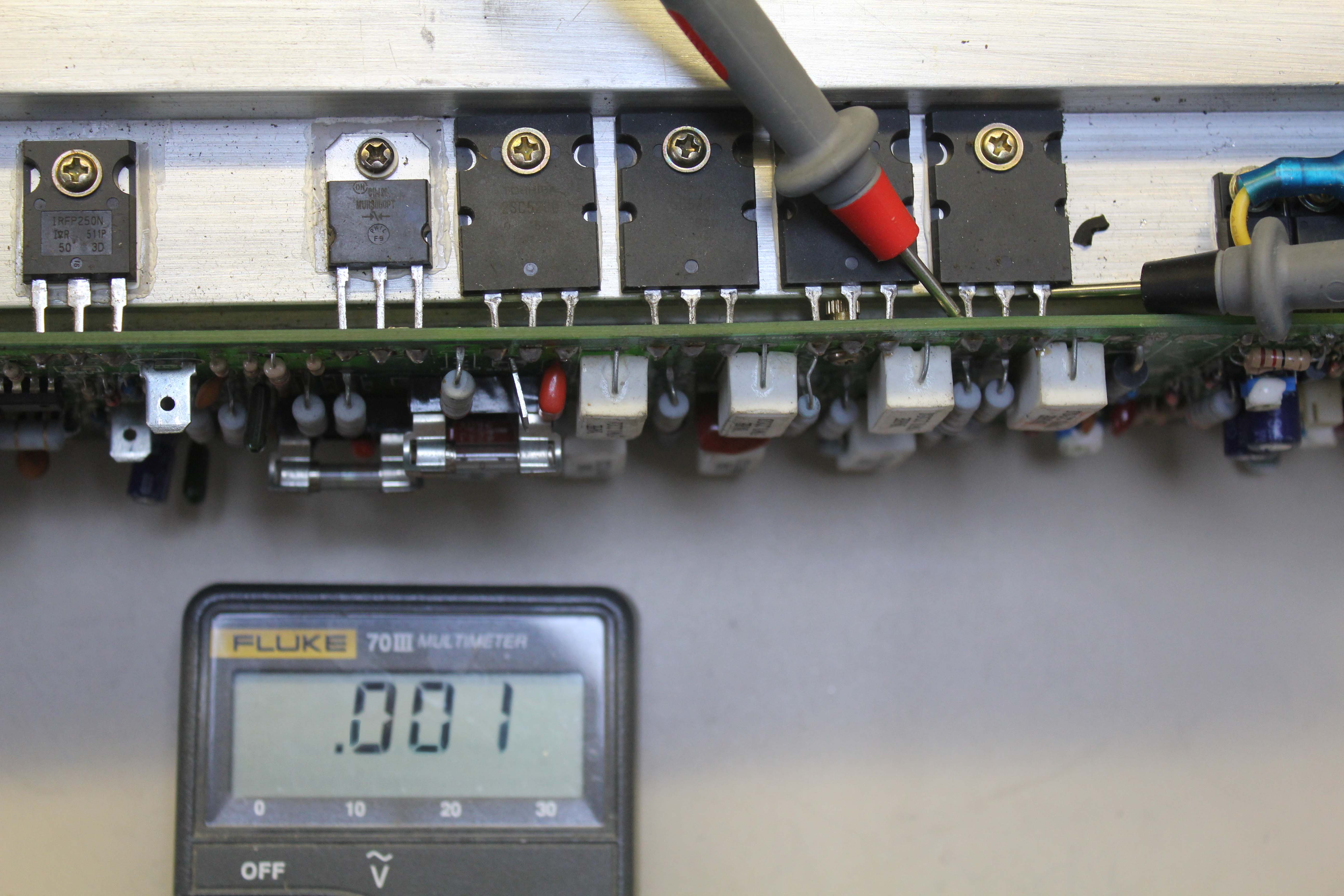
TA2440 diode test
Having identified the dead devices, cut the legs near the body, leaving enough lead on the PCB side to grab with a pair of needle nose pliers.
TA2440 channel A heatsink assembly legs cut
After making a note of which transistors go where, remove the screws and transistors. Don’t put the dead transistors in the bin. This is electrical waste – it needs to be proper WEEE disposal. Save up other WEEE waste and take it to your local tip.
TA2440 channel A heatsink assembly transistors removed
Clean off the heatsink compound with paper towels soaked in IPA. Carefully desolder the cut-off legs from the PCB using a high wattage soldering iron (at least 80W) and some thick desoldering wick. Use the wick to remove the solder so as to open up the mounting holes. You will get through a lot of wick.
TA2440 channel A heatsink assembly holes full of solder
Clean off the flux with cotton buds and IPA. The transistor mounting holes should now be nice and clean.
TA2440 channel A heatsink assembly holes free of solder
We now need some heatsink compound aka thermal paste.

heatsink compound
Apply a thin smear of the heatsink compound to the metal face of the transistor using a tooth pick, cocktail stick or similar.
Applying a thin smear of heatsink compound to the transistor
Carefully feed the transistors legs through the mounting holes. Screw the transistors to the heatsink now, before you solder them in.
TA2440 channel A heatsink assembly new transistors ready to be soldered
Solder the legs of the transistors to the PCB. Cut off the excess and clean with cotton buds and IPA.
TA2440 channel A heatsink assembly new transistors fitted
Repeat for the transistors along the other side of the PCB.
Before you put everything back together, you should clean the fluff from the front panel air intake foam, and check the rear panel fans are OK. If a fan need replacing, they are 80 mm square, 20 mm deep, 24 V DC, for example this from Farnell. Cut the PCB connector from the old fan and solder it onto the leads of the new.
Reconnect the wires and screw in the heatsink. Now for the moment of truth. If you are feeling cautious, start off with lower value fuses (1 or 2A) before fitting the proper 16A fuses.
Be very careful if you power-up the amplifier when the top cover removed. The rails are ±67.5V- the internal power supply is big enough to barbecue an ox, certainly enough to kill you.
All being well, the fans should start, the protection relays should click and all should be well. For bonus points, check the positive and negative rails on both sides of both fuses (should be around ±67.5V with no load) and remove the fuses to measure the quiescent current (Idq). I measured 19 mA on one amplifier and 25 mA on another. The positive and negative Idqs should be very close to each other in value.
TA2440 jobs a good un